
Toyota Tacoma Camshaft
Position Sensors Replacement Guide
How to change a faulty camshaft position
sensor on the 2GR-FKS 3.5L V6 engine in a 2016 to 2021 Toyota Tacoma.

By Paul B. Michaels Author & Photographer Auto Mechanic Since 1989 |
||
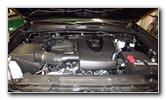 2020 Tacoma TRD Sport |
 Passenger Side of Engine |
 Two Sensors - Bank 1 |
| This automotive
maintenance tutorial was specifically written to assist owners of the third
generation (2016, 2017, 2018, 2019, 2020, 2021 and probably also the 2022
and 2023 model years) Toyota Tacoma pickup truck in changing a faulty or
failing camshaft position or "CMP" sensor. The are four camshaft position
sensors which are part of the 2GR-FKS 3.5L V6 engine's VVT-i (variable valve
timing with intelligence) system. (The procedure should be very similar for
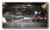
the 2TR-FE 2.7L I4 engine.) A few of the symptoms of a camshaft position sensor problem include rough idling, stalling, reduced fuel economy (lower MPG), surging, jerking, misfiring, poor acceleration and possibly a CEL / SES (check engine / service engine soon) warning light illuminated on the gauge cluster. If you have an OBDII scanner (also known as an OBD2 scan tool), some of the camshaft position sensor related DTC (diagnostic trouble codes) that you might see include the following: P0340, P0341, P0342, P0343, P0344, P0345, P0346, P0347, P0348, P0349, P0365, P0366, P0367, P0368, P0369, P0390, P0391, P0392, P0393 and P0394. Owners of other Toyota or Lexus vehicles such as the Tundra, 4Runner, Hilux, Highlander, C-HR, Avalon, Camry, Corolla, Supra, Land Cruiser, Prius, RAV4, Mirai, Sequoia, Sienna, Yaris, CT 200h, ES 300h, RX 350, GX 460, LX 570, NX 300, RX 450h, UX 200 and UX 250h may also find these DIY instructions to be helpful. The OEM part numbers are as follows: Toyota 90919-05061 and Toyota 90919-05073. Please double check the orientation of the electrical connector socket on the camshaft position sensor that you need to replace to make sure you purchase the correct part. There are two types of sensors with one having the electrical connector socket pointing straight out of the top of the sensor and the other type has the electrical connector socket pointing out from the side of the sensor housing. The tools needed to complete this procedure include a 10mm socket with a short extension bar and either a 1/4" or a 3/8" drive ratchet. The first two steps are to open the hood and locate the four sensors. There are two sensors on the left (passenger) side of the engine and another two sensors on the right (driver) side of the valve cover.
|
||
|
|
||
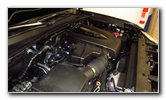
 Intake & Exhaust Sensors |
 Intake Side - Bank 1 |
 Exhaust Side - Bank 1 |
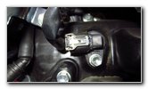
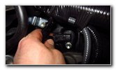
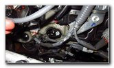
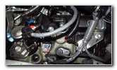
| For this tutorial,
I'll be removing and replacing the two camshaft position sensors on the left
(passenger) side of the engine. The upper sensor is labeled as the "VVT Sensor For Intake Side of Bank 1" in the service manual and it has the electrical connector orientated on the side of the sensor housing. The "Intake Bank 1" seems to be the only sensor out of the four camshaft position sensors that has the electrical connector situated off to the side. The other three sensors have the electrical connector socket pointing up out of the top of the sensor housing according to the service manual. |
||
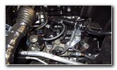
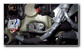
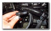
 Push In Release Tab |
 Power Plug Disconnected |
 Loosen Counterclockwise |
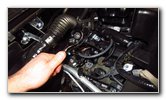
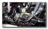
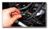
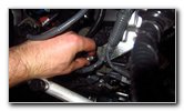
| Push in the release
tab on the electrical connector before sliding it straight off the base of
the old sensor. Loosen the bolt on the sensor by turning it in the counterclockwise direction with a 10mm socket and a 1/4" or a 3/8" drive ratchet. I had trouble loosening the bolt with my small 1/4" drive ratchet so I had to switch to using a larger 3/8" drive ratchet. |
||
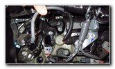
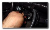
 Single Bolt Removed |
 Pull Out Old Sensor |
 OEM Part Number |
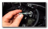
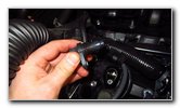
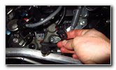
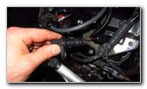
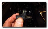
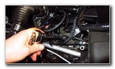
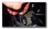
| Spin out the bolt
and set it aside in a safe place. You'll notice that the bolt is covered in a green threadlocking adhesive compound. This threadlocker should be similar to Loctite Green which is low viscosity and has wicking properties for securing bolts after the parts have already been assembled. The green threadlocker is categorized as "medium-to-high-strength" and can be removed by applying heat and using hand tools. It was difficult to remove the bolt but I didn't have to apply heat since the engine was already warm. Rotate the old sensor back and forth a few times to make sure it isn't stuck in the valve cover. Pull the old sensor straight out of the engine. |
||
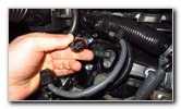
 Line Up New Sensor |
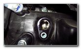 Sensor Port (Opening) |
 Install New Sensor |
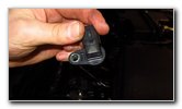
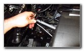
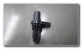
| The part number for
the "Intake Side of Bank 1" sensor with the electrical connector pointing
out to the side is genuine OEM
Toyota 90919-05061. Insert the new sensor into the valve cover. Line up the bolt hole in the new sensor with the corresponding hole in the valve cover. |
||
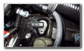
 Spin In 10mm Bolt |
 Push On Power Plug |
 Lower - Exhaust Side B1 |
| Since Loctite Green
may require heat for removal, I chose to use a drop of
Loctite Blue (medium strength -
removable with hand tools) on the sensor bolt. Spin in the 10mm bolt and tighten it in the clockwise direction until it is snug. Try to avoid over tightening the bolt to prevent from cracking the plastic sensor housing. If you insist on using a torque wrench, the specification for tightening the camshaft position sensor bolt in the service manual is 7 lb-ft (or 10 N-m) of torque. The lower sensor on the passenger side of the valve cover is the "Exhaust Side of Bank 1" sensor. |
||
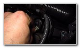
 Disconnect Power Plug |
 Loosen Counterclockwise |
 Spin Out Single Bolt |
| Disconnect the
power plug. Loosen the bolt by turning it in the counterclockwise direction with the 10mm socket and the 3/8" drive ratchet. Set the bolt aside in a safe place. |
||
 Remove Old Sensor |
 Inspect Old Sensor |
 OEM Part Number |
| Rotate the old
sensor back and forth a few times to make sure it isn't stuck in the valve
cover.
Avoid just forcing the sensor straight out to prevent from having the rubber gasket tear apart and fall down into the port (opening) in the valve cover. Remove the old sensor. The OEM part number is Toyota 90919-05073. |
||
 Lower Sensor Port |
 Install New Sensor |
 Tighten 10mm Bolt |
| Install the new
sensor into the port. Line up the bolt holes. Spin in the bolt a few turns by hand in the clockwise direction to make sure it doesn't become cross threaded. Tighten the bolt with the 10mm socket and a 3/8" drive ratchet until it is snug. |
||
 Attach Electrical Connector |
 New Sensors Installed |
 Test 3.5L V6 Engine |
| Push on the
electrical connector. You should feel or hear the electrical connector "click" securely into place. Re-attach the negative terminal to the "-" battery post. Start the engine and listen closely for any strange noises. If you do hear a strange sound, immediately turn off the ignition and double check your work. If you have an OBDII scanner check for any DTC (diagnostic trouble codes), clear the codes, turn off the ignition and turn it back on to see if they re-appear. If you still have the same issues, it might be caused by a faulty crankshaft position sensor (also known by the acronyms "CPS" or "CKP") which is part number Toyota 90919-05098. There was a recall of the crankshaft position sensor for about 32,000 Tacoma trucks from the 2016 and 2017 model years. Another possibility is a defective VVT solenoid (also known as the oil control valve). Be sure to write down the sensor change in your truck's service records. Please
check out all of the
2016-2021 Toyota Tacoma DIY Repair & Maintenance Guides. |
||
| If you found this guide to be helpful,
please consider making a small donation by clicking on the PayPal.com
"Donate" button located to the right of this paragraph. Thank you!
(Note: I am not a registered charity. Donations are not tax deductible.) |