
Toyota
Corolla PCV Valve Replacement Guide
How to change the PCV valve in a 10th
generation 2009, 2010, 2011, 2012 & 2013 Toyota Corolla with the 2ZR-FE.

By Paul B. Michaels Author & Photographer Auto Mechanic Since 1989 |
||
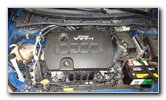 2010 2ZR-FE 1.8L I4 |
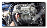
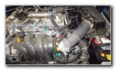
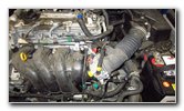
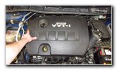
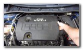 Pull Off Plastic Cover |
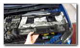 Engine Cover Removed |
| This
automotive "how-to" guide was specifically written to assist owners
of the 10th generation (2009, 2010, 2011, 2012 and 2013) Toyota Corolla
in checking or changing the PCV (positive crankcase ventilation)
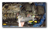
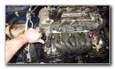
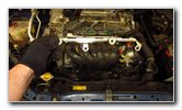
valve on the 2ZR-FE 1.8L I4 engine. A few of the symptoms of a failing, faulty, clogged or stuck open PCV valve include a rough idle, misfiring, backfiring, surging, jerking, increased oil consumption, oil leaks, a CEL / SES (check engine / service engine soon) warning light, white or blue smoke from the exhaust pipe, an oily engine air filter element and reduced fuel economy (lower MPG). There is no mention of the PCV valve in the maintenance schedule section of the Corolla owner's manual. I chose to replace the valve as part of my 100K mile service (done at 95,000 miles). If you do a lot of stop-and-go city driving, you may want to change it every 60K miles. On the other hand, if you mostly drive on the highway, you could possibly wait until 100K or 120K miles if the engine has none of the symptoms listed above. Owners of other Toyota, Lexus or Scion vehicles such as the Yaris, Matrix, Prius, Camry, RAV4, Sienna, Tacoma, Tundra, FJ Cruiser, Venza, Highlander, Avalon, Sequoia, Land Cruiser, Allion, Premio, Auris, IS 250, ES 350, GS 350, tC, xB, xD, iQ and FR-S may also find these DIY instructions to be helpful. The OEM (original equipment manufacturer) part number for the PCV valve is Toyota 12204-37010 (also known as part # 1220437010). I highly recommend buying the genuine Toyota part, but here are a few compatible replacement aftermarket valves with their part numbers: Mikkuppa QPV005, Standard Motor Products V512 and OES W0133-1811308-OES. The tools required to complete this procedure include a pair of pliers, a Phillips head screwdriver, a 10mm socket with a 1/4" drive ratchet, a 12mm socket with an extension bar, a 3/8" drive ratchet, a 22mm socket and a 1/2" drive ratchet. The first few steps are to open the hood, pull off the plastic engine cover and set the cover aside in a safe place. |
||
|
|
||
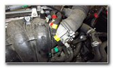
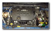
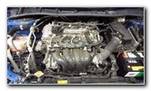 Top of Engine Exposed |
 Clean Off With Vacuum |
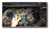 Colored Electrical Tape |
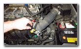
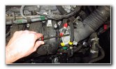
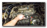
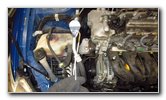
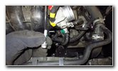
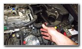
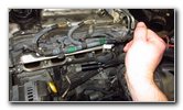
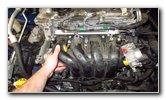
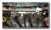
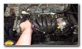
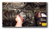
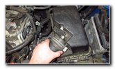
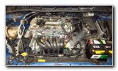
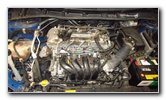
| If you have an air
compressor or a wet/dry shop vacuum, clean off any sand or debris from the
top of the intake manifold to help prevent from having a foreign object fall
down into the engine. To make this tutorial easier to follow, I chose to label the four rubber hoses that need to be disconnected with colored electrical tape. There is one hose on the top of the valve cover, two hoses attached to the top of the throttle body and the fourth hose is down below on the right (driver) side of the intake manifold. |
||
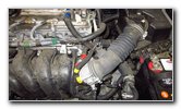 Marking Hoses With Tape |
 Two Coolant Hoses |
 Four Hoses Marked |
|
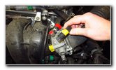
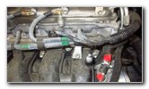
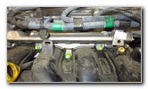
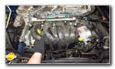
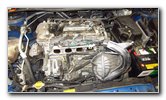
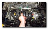
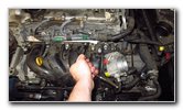
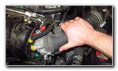
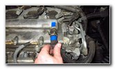
Please take a look at Picture # 8 to see the location of the two coolant hoses that should be left attached to the throttle body to prevent from having coolant leak out. I marked the two hoses with the word "COOLANT" in red letters. If you look at Picture # 9, you'll see the four hoses that have to be removed marked with colored electrical tape. From the top to the bottom, they are "Blue", "Red", "Yellow" and "Green". For the rest of this guide, I'll refer to these hoses by their assigned colors. |
||
 Red, Yellow, Green |
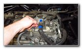 Slide Back Hose Clamp |
 Pull Off "Blue" Hose |
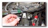
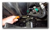
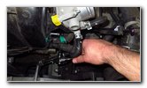
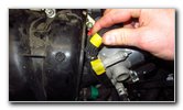
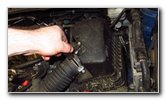
| Pinch the two tabs
on the spring clip attached to the "Blue" hose on the top of the engine's
valve cover. Slide the clamp away from the engine. Pull the "Blue" hose off the valve cover. |
||
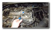
 Pull Off "Yellow" Hose |
 Pinch Hose Clamp |
 Slide Back Hose Clamp |
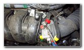
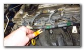
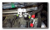
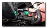
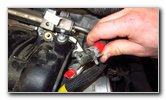
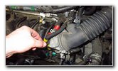
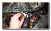
| Pull the "Yellow"
hose off the black plastic nipple on the intake manifold near the throttle
body. Use a pair of pliers to pinch together the two tabs on the metal clamp that secures the "Red" hose to the throttle body. Slide the hose clamp back away from the end of the hose. Pull the "Red" hose off the throttle body. Move to the "Green" hose located at the bottom right of the intake manifold below the throttle body. Pinch the spring clamp to release it and slide it back away from the end of the hose. |
||
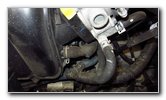
 Push Off Lower Hose |
 Four Hoses Disconnected |
 Loosen Hose Clamp |
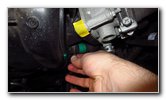
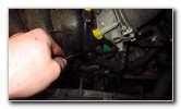
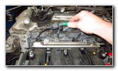
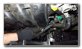
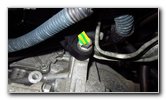
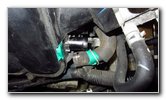
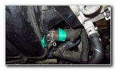
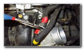
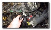
| Push or pull the
"Green" hose off the bottom right of the intake manifold. Loosen the clamp that secures the air intake hose to the throttle body by turning the Phillips head screw in the counterclockwise direction. |
||
 Phillips Counterclockwise |
 Pull Hose Off Air Box |
 Hose Off Throttle Body |
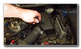
| Loosen the clamp
that secures the air intake hose to the engine air filter box by turning it
in the counterclockwise direction with a Phillips head screwdriver. Pull the air intake hose off the engine air filter housing and the throttle body. |
||
 Air Intake Hose Removed |
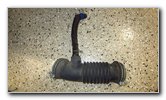 Set Aside Air Intake Tube |
 Wire Harness - Bolt |
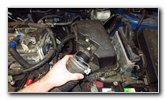
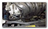
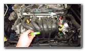
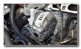
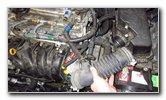
| Set the rubber air
intake hose aside in a safe place. Locate the wire harness that runs along the top of the intake manifold. On my 2010 Corolla S, the fuel injector wire harness has faded green and black electrical tape on it. |
||
 Loosen Counterclockwise |
 Single Bolt Removed |
 Pry Out Plastic Pop Rivet |
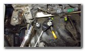
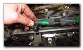
| Loosen the single
bolt on the small trapezoid shaped silver metal piece attached to the intake
manifold and the top wire harness. Turn the bolt in the counterclockwise direction with the 10mm socket and a 1/4" drive ratchet. Set the bolt aside in a safe place. Use a pop rivet removal tool to pull the plastic fastener on the left side of the harness out of the intake manifold. You might also be able to use a flat head screwdriver or a pair of needle nose pliers to pull out the pop rivet. |
||
 Plastic Fastener Removed |
 Lower Wire Harness |
 Lower Harness Fasteners |
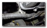
| Locate the wire harness situated at the bottom of the intake manifold. | ||
 Pry Out Pop Rivet |
 Lower Left Detached |
 Lower Right Pop Rivet |
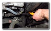
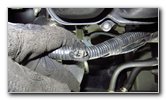
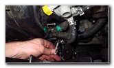
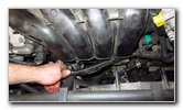
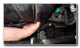
| Pry out the pop
rivet at the bottom left and the pop rivet at the bottom right of the intake
manifold. Make sure that the lower wire loom is separated from the intake manifold. |
||
 Lower Right Detached |
 Yellow / Green Tape |
 6 Fasteners - Labeled |
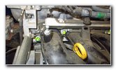
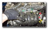
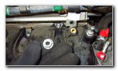
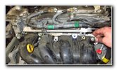
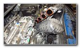
| The black plastic
intake manifold assembly is secured to the engine by six fasteners. There are four bolts and two nuts. I marked the bolts and nuts with the green / yellow electrical tape to make it easier for you to see them. The fasteners are numbered in the pictures with # 1 being on the far left (passenger) side and # 5 on the far right (driver) side. The # 6 fastener is the bolt situated on the bottom right (driver) side of the intake manifold. |
||
 Bolts # 2, 3, 4 |
 Bolts # 4 & 5 |
 Lower Right - Bolt # 6 |
 Lower PCV Hose |
 Loosen Counterclockwise |
 Magnet Catch Bolts Nuts |
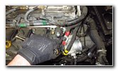
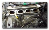
| Loosen the five
fasteners along the top of the intake manifold with the 12mm socket and a
3/8" drive ratchet. If you have a magnetic pick-up tool, hold it below the two nuts as you remove them so that they don't fall down and become lost in the engine bay. I just attached a magnet to the end of a piece of wire hanger with some tape. |
||
 Bolt # 1 Removed |
 # 2 - Remove Nut |
 Magnet - Catch Nut |
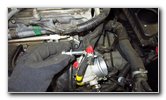
| Remove the # 1
bolt, the # 2 nut, the # 3 bolt, the # 4 nut and the # 5 nut on the top of
the intake manifold. Set the fasteners aside in a safe place. |
||
 Loosen Bolt # 3 |
 # 3 Bolt Removed |
 Loosen # 4 Nut |
 # 4 Nut Removed |
 Remove # 5 Bolt |
 # 5 Bolt Removed |
 Loosen # 6 Bolt |
 # 6 Bolt Removed |
 Fasteners Labeled |
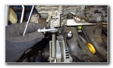
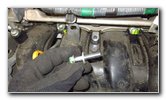
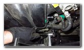
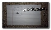
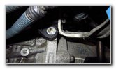
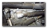
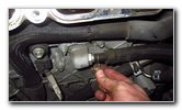
| Remove the # 6 bolt
situated at the bottom right (driver) side of the intake manifold by turning
it in the counterclockwise direction with the 12mm socket and a 3/8" drive
ratchet. As a precautionary measure, I kept the various fasteners organized by number on a piece of paper. The 12mm intake manifold bolts all seemed to be the same, but I didn't want to mix them up. |
||
 # 6 Lower Bolt Location |
 Pull Off Metal Plate |
 Metal Bracket Removed |
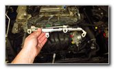
| Pull the silver
metal bracket off the top of the intake manifold. Set the bracket aside in a safe place. |
||
 Move Aside Hoses |
 Pull Off Intake Manifold |
 Intake Manifold Removed |
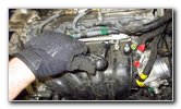
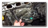
| Carefully pull the
intake manifold off the engine. Avoid using excessive force. The intake manifold should come off relatively easily. Gently rotate the intake manifold towards the right (driver) side of the engine bay. Rest the manifold on the 12V automotive battery. |
||
 Red / Orange Gasket |
 Old PCV Valve Exposed |
 PCV Valve Housing |
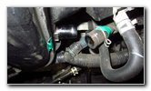
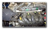
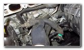
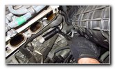
| Inspect the red /
orange colored rubber gasket on the intake manifold. If the gasket appears torn, dry rotted or damaged in any way, it should be replaced with a new one. The OEM part number for the intake manifold gasket is Toyota 17177-0T020 (or 171770T020). Locate the PCV valve housing situated just below the # 3 intake. |
||
 Pinch Clamp - Slide Back |
 Pull Off Rubber Hose |
 PCV Hose Removed |
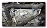
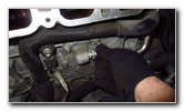
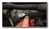
| Squeeze the two
tabs on the hose clamp and slide it back away from the PCV valve. Pull the rubber hose off the old PCV valve. Set the hose aside in a safe place. |
||
 New Craftsman Socket |
 Socket & 1/2" Ratchet |
 Loosen Counterclockwise |
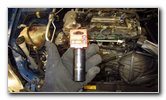
| To remove the old
valve, you'll need a 22mm socket with a 1/2" drive ratchet. I bought a Craftsman 22mm deep well impact socket but you may be able to use a standard shallow 22mm socket. Loosen the old valve by turning it in the counterclockwise direction. |
||
 Spin Out Old Valve |
 Old Valve Removed |
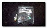 New OEM Toyota PCV |
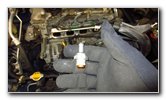
| Spin out the old
bolt the rest of the way by hand. You'll notice that both the old and new valves have threadlocker adhesive on the threads. The OEM part number for the PCV valve is Toyota 12204-37010. |
||
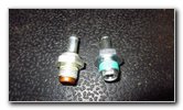 New Vs. Old Valve |
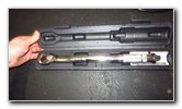 Torque Wrench |
 Socket & Torque Wrench |
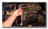
| If you have a torque wrench, the PCV valve should be tightened to the service manual specification of 20Nm which is equivalent to about 14.75 lb-ft of torque. | ||
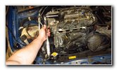
 Spin In New PCV Valve |
 Tighten New Valve |
 Easy Access Alternator |
| Spin in the new PCV
valve a few turns by hand in the clockwise direction to make sure it doesn't
become cross threaded. Tighten the new valve by turning it in the clockwise direction with the 22mm socket and a 1/2" drive ratchet. The new valve might be difficult to turn at first due to the dried thread locking adhesive fluid on the threads. Continue tightening the new valve to the service manual specification of 20 Newton-meters or 14.75 lb-ft of torque. Try to avoid over tightening the valve to prevent from damaging the threads or cracking the aluminum housing. (If your car needs a new alternator, now would be a good time to replace it. There is plenty of working room around the alternator with the intake manifold removed.) (If your car needs a new knock sensor, the knock sensor is located just to the left of the PCV valve housing and below the # 2 intake.) |
||
 PCV Valve Hose |
 Push Hose Over PCV |
 Replace Intake Manifold |
| Push the rubber
hose back over the nipple on the end of the new PCV valve. Route the other side of the hose (with the green tape) towards the right side of the engine. Slide the clamp back into place over the hose and the PCV valve's nipple. Make sure the hose is securely in place. Wipe off any debris from the intake manifold gasket. Carefully lower the intake manifold back into place over the front of the engine. |
||
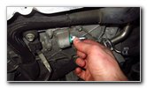
 Line Up "Green" Hose |
 Insert Bolt # 6 |
 Silver Metal Bracket |
| Make sure the hose
from the PCV valve (marked with green tape) is in the correct position at
the bottom right corner of the intake manifold. Spin in the # 6 bolt at the bottom right of the intake manifold. |
||
 Lower In Metal Bracket |
 Replace Bolt - # 1 |
 Replace Nut - # 2 |
| Lower the silver
metal bracket down over the top of the intake manifold. Replace the fasteners. |
||
 Replace Bolt - # 3 |
 Replace Nut - # 4 |
 Replace Bolt - # 5 |
| Spin in the bolt #
1, nut # 2, bolt # 3, nut # 4 and bolt # 5 along the top of the intake
manifold. Do not fully tighten any of the fasteners until they are all in place. Once all 6 fasteners are attached, tighten them to the service manual specification of 28 Nm or about 20.65 lb-ft of torque. Double check that all of the bolts and nuts are tight before moving on to the next steps. |
||
 Tighten Bolt - # 6 |
 Line Up "Green" Hose |
 Lower Hose Secured |
| Tighten the bolt #
6 at the bottom right of the intake manifold. Push the "Green" hose on to the bottom of the intake manifold near bolt # 6. Secure the spring clip clamp over the end of the "Green" hose. |
||
 Push On "Yellow" Hose |
 Push On "Red" Hose |
 Secure Hose Clamp |
| Push the "Yellow"
hose back over the black plastic nipple on the top right of the intake
manifold near the throttle body. Push the "Red" hose on to the throttle body. Secure the metal hose clamp over the end of the "Red" hose. |
||
 Line Up Air Intake Hose |
 Push Hose On Air Box |
 Hose On Throttle Body |
| Line up the air
intake hose with the smaller "Blue" hose near the top of the engine. Push the rubber hose on to the engine air filter box and the throttle body. |
||
 Tighten Clamp Clockwise |
 Tighten Hose Clamp |
 Push On "Blue" Hose |
| Tighten the two
hose clamps on the air intake hose by turning the screws in the clockwise
direction with a Phillips head screwdriver. Push the "Blue" hose on to the metal nipple on the top of the valve cover. |
||
 Wire Loom Bracket Bolt |
 Tighten Bolt Clockwise |
 Push In Pop Rivets |
| Re-attach the
trapezoid shaped metal bracket for the fuel injector wire harness by
tightening the 10mm bolt in the clockwise direction until it is snug. Push in the pop rivets for the lower wire harness into their mounting holes. |
||
 Wire Loom Secured |
 Secure Top Wire Harness |
 Done Re-Assembling |
| Push the pop rivet
for the upper wire harness into the mounting hole on the top left of the
intake manifold. Double check that the wire harnesses, fasteners and hoses are all properly installed. |
||
 Removed Color Tape |
 Push On Plastic Cover |
 Engine Cover Secured |
| Lower the plastic
cover back into place and push on it to secure the four rubber friction
fasteners to the metal pegs on the top of the engine. Start the engine and listen closely for any strange sounds. If you do hear any strange noises, immediately turn off the engine and double check your work. Be sure to inspect the rubber hoses for any splits, tears, cracks or other damage. Don't forget to write down the procedure in your vehicle's service records. For more, check out my other Corolla DIY tutorials at the links below - 2009-2013 Toyota Corolla Repair & Maintenance Guides |
||
| If you found this guide to be helpful,
please consider making a small donation by clicking on the PayPal.com
"Donate" button located to the right of this paragraph. Thank you!
(Note: I am not a registered charity. Donations are not tax deductible.) |