
Acura MDX
Alternator Replacement Guide
How to replacing a failing or dead
alternator in a 1st generation 2001 to 2006 Acura MDX SUV with the part numbers.

 VTEC 3.5L V6 Engine |
 Left - Passenger Side |
 Old Alternator - 167K Miles |
| This
automotive maintenance tutorial was specifically created to assist
owners of the first generation (2001, 2002, 2003, 2004, 2005 & 2006)
Acura MDX in changing a weak or failed alternator or "generator" for
the 12 volt charging system on the VTEC 3.5 liter V6 engine. Owners of other Acura or Honda vehicles such as the RDX, ILX, TLX, RLX, TL, CL, RSX, RL, TSX, ZDX, NSX, Integra, Pilot, Accord, Civic, Fit, Clarity, CR-V, CR-Z, HR-V, Odyssey, Element and Ridgeline with the VTEC 3.5L V6 engine may also find these DIY instructions to be helpful. The original "OEM" alternator is part number Denso 210-0580 (also known as part # 2100580). The tools needed to complete this procedure include a flathead screwdriver, a 10mm socket with a 1/4" drive ratchet, a 12mm socket with a 3/8" drive ratchet and a 14mm socket with a long 18" or 24" 1/2" drive breaker bar to release the serpentine belt. |
||
|
|
||
I highly recommend buying the high quality OEM Denso 210-0580 alternator that Acura included with the MDX. Here are a few other compatible replacement alternators with their part numbers: TYC 2-11151, DB Electrical AND0339, Bosch AL1297X, Remy 12723, Discount Starter & Alternator 11151N, ECCPP AND0339, Quality Rebuilders 11151 and the Acura 31100-RJA-A02. To test your old alternator and battery before purchasing any new parts, I recommend using a digital multimeter tool. Place the leads of the multimeter on the 12V battery with the engine off. The voltage should be just above 12V such as 12.2V or 12.3V (unless you were driving around with a failing alternator and the battery light lit up on the dash for many miles). Then start the engine and check the multimeter again. If the alternator is working properly the voltage should be anywhere from above 13V to just over 14V. If the voltage with the engine running is well below 13V, the alternator is failing and should be replaced. While you are replacing the alternator, I recommend charging the 12V battery with a Battery Tender. I like to attach my Battery Tender Jr. to our car batteries at least once a month to fully charge them since we tend to drive many short trips that can drain the battery and not allow the alternator enough time to fully charge them again. |
||
 Remove Oil Dipstick |
 Oil Dipstick Removed |
 P/S & Coolant Bottles |
| My first step was
to pull the plastic orange handled oil dipstick out of the engine.
I didn't want to risk breaking the plastic handle while removing or installing the alternator. Set the dipstick aside in a safe place. Push a small clean towel or rag into the dipstick port to keep debris from falling into the engine. For better access to the alternator, you'll need to release the power steering reservoir and the coolant overflow bottle. |
||
 Pry Back Retaining Clip |
 Pull Up Power Steering Reservoir |
 Coolant Overflow Bottle |
| Use a flathead
screwdriver to gently pry back the release tab on the front of the power
steering reservoir. Lift the P/S reservoir bottle straight off its mounting bracket. Do not disconnect the hoses. Then lift the white translucent plastic coolant overflow bottle straight off its mounting bracket. |
||
 Pull Up Coolant Reservoir |
 Bottles Out of the Way |
 12V Automotive Battery |
| Move the two
bottles away from the pulleys and belt to just behind the passenger side
headlight assembly. Next, move to the 12V automotive battery on the right (driver) side of the engine bay. |
||
 Loosen Counterclockwise |
 Disconnect Negative Cable |
 Cover & Tuck Away |
| Loosen the nut on
the "-" negative terminal by turning it in the counterclockwise direction
with a 10mm socket and a 1/4" drive ratchet. Pull the negative terminal straight off the "-" battery post. Wrap the terminal in a small towel and tuck it away on the side of the battery to help prevent accidental electrical contact. |
||
 Cover Oil Dipstick Port |
 Rubber Connector Cover |
 Output Cable |
| Then move back to
the left front corner of the engine where the alternator is attached. Pull the large black rubber boot off the main output B+ connector and terminal. |
||
 Loosen Counterclockwise |
 12mm Nut Removed |
 Pull Off Output Connector |
| Loosen the nut on
the output cable connector by turning it in the counterclockwise direction
with a 12mm socket and a 3/8" drive ratchet. Set the 12mm nut aside in a safe place. Pull the output cable off the B+ terminal stud. |
||
 Alternator Output Stud |
 Voltage Regulator Plug |
 Slide Off Rubber Cover |
| Then locate the
external voltage regulator electrical connector that goes to the PCM (powertrain
control module) on the right side of the
alternator below the B+ main output terminal. Slide back the grey rubber dust boot to expose the green plastic connector. |
||
 Push In Release Tab |
 Green Connector Removed |
 Green Plastic Plug |
| Gently push in the
release tab on the front of the connector before sliding it straight out of
its socket. Try to avoid using excessive force. The regulator connector should slide out relatively easily. |
||
 Loosen 10mm Bolt |
 10mm Bolt Removed |
 Wire Bracket Removed |
| The two cables are
attached to a small metal bracket on the top of the alternator. Loosen the 10mm bolt that secures the bracket in place by turning it in the counterclockwise direction. Set the 10mm bolt aside in a safe place. |
||
 Wire Loom Retainer |
 Gently Pry Back Clip |
 Pull Off Metal Mount |
| Further back in the
engine bay, you'll see another output cable wire loom retainer attached to a
bracket. Gently pull back the release tab and lift the wire loom off the bracket. |
||
 Purple Pop Rivet Connector |
 Squeeze Prongs With Pliers |
 Wire Retainer Released |
| Then use a pair of needle nose pliers to release the purple plastic pop rivet that secures the regulator wire loom to the small metal bracket. | ||
 Tuck Away Regulator Cable |
 Tuck Away Output Cable |
 14mm Socket & Breaker Bar |
| Move the regulator
cable out of the way such as under the left edge of the plastic engine
cover. Move the B+ output cable to just below the cowl and behind the electrical fuse box. Once both of the electrical cables are safely out of the way, you can move on to releasing the serpentine accessory belt. |
||
 Attach Socket To Tensioner |
 Tensioner Pulley & 14mm |
 Lift Up Handle - Release Tension |
|
Attach the 14mm socket to an 18" or 24" long 1/2" drive breaker bar. Place the socket over the bolt head on the tensioner pulley located behind the alternator, below the power steering pulley and just above the small idler pulley.
Firmly lift the breaker bar handle and rotate it back towards the firewall to release the tension on the belt. |
||
 Slip Belt Off Alternator |
 Move Serpentine Belt Back |
 Alternator Bracket - Front |
| Very carefully slip
the serpentine belt off the alternator pulley. Avoid placing your fingers in between the belt and any of the pulleys. Move the serpentine belt back away from the alternator. If you aren't planning on replacing the serpentine belt, try to avoid pulling it off the other pulleys to save yourself time later on. Next, locate the black metal bracket on the top of the alternator and the two 12mm bolts that hold it into place. |
||
 Two 12mm Bolts - Top |
 Loosen Front Bolt |
 Front Bolt Loosened |
| The front lower
12mm bolt is attached to the top of the alternator. The rear 12mm bolt is attached to the engine's cylinder block. Loosen the front bolt by turning it in the counterclockwise direction with a 12mm socket and a 3/8" drive ratchet. |
||
 Rear Top 12mm Bolt |
 Loosen 2nd 12mm Bolt |
 Bottom 14mm Bolt |
| Then loosen the
rear bolt that is situated slightly higher up by turning it in the
counterclockwise direction with the 12mm socket and a 3/8" drive ratchet. Do not fully remove either bolt. Move to the rear bottom corner of the alternator and locate the larger 14mm bolt. |
||
|
|
||
 Larger Bolt Below Alternator |
 Loosen Counterclockwise |
 Loosening 14mm Bolt |
| Loosen the bottom bolt by turning it in the counterclockwise direction with a 14mm socket and a 1/2" drive or 3/8" drive ratchet. | ||
 Long 14mm Bolt Removed |
 Long 12mm Front Top Bolt |
 Remove Top Rear Bolt |
| Spin out the long
14mm bolt by hand and set it aside in a safe place. Then remove the two 12mm bolts on the top of the alternator. The slightly longer silver metal 12mm bolt is attached to the top of the alternator on the front of the black metal bracket. The shorter bronze / copper / gold colored bolt is attached to the engine block on the rear of the black metal bracket. |
||
 Short Rear 12mm & Bracket |
 Old Alternator Loose |
 Lift Out Old Alternator |
| Set the two 12mm
bolts and the black metal bracket aside in a safe place. I was able to easily lift the old alternator out of the engine bay. If you have trouble lifting out the old alternator, you may need to use a pry bar to loosen it from the lower mounting bracket. |
||
 Old Alternator Removed |
 Worn Out After 167,000 Miles |
 New Denso Alternator |
| The original Denso
alternator from 2006 lasted for just over 167,000 miles.
So I purchased the OEM quality Denso 210-0580 remanufactured alternator. I'm hoping it will last at least another 150,000 miles. |
||
 Remanufactured |
 Brown Plastic Regulator Socket |
 Mounting Location |
| Clear away any debris or dirt on the lower mounting location to make sure the new alternator will rest evenly. | ||
 Lower Mounting Bracket |
 Position New Alternator |
 Alternator In Mounting Bracket |
| Carefully lower the
new alternator into the engine bay past the coolant hoses. Push the "ear" at the bottom of the new alternator into the mounting bracket and line up the bolt holes. |
||
 Medium Blue Loctite |
 Spin In Long 14mm Bolt |
 Top Black Metal Bracket |
| I chose to place a
small amount of Loctite Blue
medium strength threadlocker liquid on the three bolts to help prevent them
from vibrating loose in the future. Spin in the long 14mm bolt into the bottom of the alternator a few turns in the clockwise direction by hand to prevent it from becoming cross thread. I had labeled the correct orientation of the black metal bracket on a paper towel. |
||
 Line Up Metal Bracket |
 Spin In Long Front 12mm Bolt |
 Spin In Small 12mm Rear Bolt |
| Lower the black
metal bracket down into place on the top front of the new alternator. Spin in the longer 12mm silver metal bolt into the front of the bracket and through the alternator. Then spin in the shorter bronze colored 12mm bolt into the hole on the rear of the bracket and into the cylinder block. Starting the bolts by hand will help prevent them from becoming cross threaded. |
||
 Spin In Clockwise |
 Tighten Lower 14mm Bolt |
 |
| Tighten the three bolts in the clockwise direction to just past hand tight. | ||
 Bottom Bolt Tightened |
 Tighten Top Front 12mm |
 Three Bolts Secured |
| Double check that
the bottom 14mm bolt and the two top 12mm bolts are tight before moving on
to the next steps. (If you would like to tighten the bolts with a torque wrench, the service manual values are as follows: 14mm bolt - 33 lb-ft and two 12mm bolts - 16 lb-ft of torque.) |
||
 14mm Socket - Belt Tensioner |
 Output Cable Connector |
 Output B+ Stud / Post |
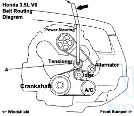
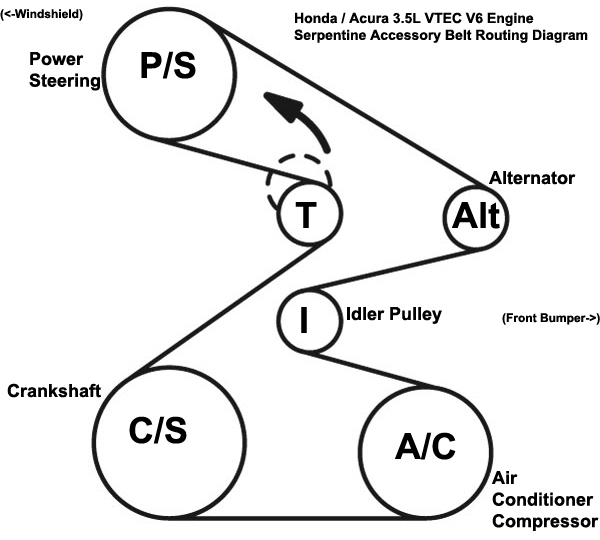
| The next step is to
re-attach the serpentine belt to the alternator pulley. Place the 14mm socket over the tensioner pulley with a long 1/2" drive breaker bar. Rotate the breaker bar or ratchet handle back towards the windshield. Carefully slip the serpentine belt over the alternator pulley. I included a serpentine accessory belt routing diagram just in case you need to re-route the belt over the other pulleys as well.
|
||
 Lower Connector Over Stud |
 Spin On 12mm Nut |
 Tighten 12mm Nut |
| Lower the ring
terminal over the B+ output stud. Spin on the 12mm nut a few turns by hand in the clockwise direction. Tighten the nut in the clockwise direction with the 12mm socket and a 3/8" drive ratchet until it is snug. If you live in a very humid climate, you may choose to apply some dielectric grease to the B+ terminal and ring connector to help prevent corrosion (rust) and ensure a reliable electrical connection. |
||
 Push On Rubber Cover |
 Voltage Regulator Connector |
 Brown Plastic Socket |
| Push the rubber
dust boot over the output terminal. Next, route the external voltage cable back into place. Locate the brown plastic socket on the right (driver) side of the alternator. |
||
 Push In Electrical Connector |
 Purple Wire Retainer |
 Pop In Purple Pop Rivet |
| Push the green
plastic voltage regulator power plug straight into the socket. The release button should be situated at the front of the connector facing towards the radiator. Slide the grey rubber cover over the voltage regulator electrical connector. Push the purple pop rivet wire loom retainer back into the hole on the black metal bracket attached to the output cable. |
||
 Line Up Wire Bracket |
 Tighten 10mm Bolt |
 Push On Wire Loom Clip |
| Attach the cable
bracket to the top of the alternator bracket by replacing the 10mm bolt. Tighten the 10mm bolt in the clockwise direction until it is snug. Re-attach the retaining clip for the output cable to the bracket near the power steering pump pulley. Double check that the two electrical cables are properly routed. They should be clear of all the pulleys and serpentine belt. |
||
 Lower In P/S Reservoir |
 P/S Bottle Secured |
 Push In Coolant Bottle |
| Lower the power
steering fluid reservoir tank into its mounting bracket. It should "click" securely into place. Then push the coolant overflow bottle down into its mounting bracket. |
||
 Two Bottles Secured |
 Replace Oil Dipstick |
 Alternator Replaced |
| Double check that
the coolant overflow bottle and power steering fluid reservoir are securely
attached. Pull the small towel out of the oil dipstick port. Push the oil dipstick back into place. |
||
 "-" Negative Terminal |
 Tighten 10mm Clockwise |
 12V Battery Connected |
| Move to the right
side of the engine bay. Push the negative terminal back on to the "-" battery post. Tighten the 10mm terminal nut by turning it in the clockwise direction until it is snug. Try to avoid over tightening the terminal nut to prevent from damaging the battery post which could lead to an acid leak. |
||
 Enter Radio Security Code |
 Test Alternator Output - Multimeter |
 167,426 Miles 2006 MDX |
| Since the battery
was disconnected, you will need to enter the security code for your stereo. On some Acura or Honda models, the radio security code will be on a white sticker attached to either the inside or outside of the glove box. Our MDX has a anti-theft radio code card inside the leather binder that contains the owner's manual. Turn the ignition switch to the "ON" position but do not start the engine. You should see "CODE" displayed on the radio. Enter the security code into the radio by using the numbered preset radio station buttons "1, 2, 3, 4, 5, 6". To test that the new alternator is working properly, connect the multimeter leads to the battery with the engine running. The voltage should be anywhere from just above 13 volts to just over 14 volts. Be sure to record the alternator change in your vehicle's service records. For more,
please check out all of my
2001-2006 Acura MDX DIY Repair & Maintenance Guides. |
||
| If you found this guide to be helpful,
please consider making a small donation by clicking on the PayPal.com
"Donate" button located to the right of this paragraph. Thank you!
(Note: I am not a registered charity. Donations are not tax deductible.) |