
Chevrolet
Tahoe Intermediate Steering Shaft Replacement Guide
How to change the intermediate steering
shaft & stop the clunking noise in a 2nd generation 2000 to 2006 GM Chevy Tahoe.

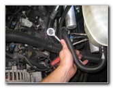
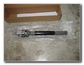 New Steering Shaft |
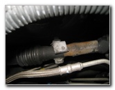
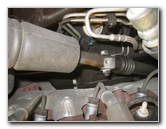 Old ISS In Engine Bay |
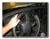
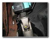
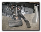
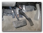 Brake & Gas Pedals |
|
This automotive maintenance tutorial was specifically written to assist owners of the second generation (2000, 2001, 2002, 2003, 2004, 2005 & 2006) GM Chevrolet Tahoe SUV in changing a faulty intermediate steering shaft which causes a clunking, clicking, ticking or popping sound in the steering column. Owners of other General Motors GMT800 series SUV, truck or van vehicles such as the Chevy Silverado, Suburban, Avalanche, GMC Yukon, Sierra, Hummer H2 and the Cadillac Escalade may also find these DIY instructions to be helpful. The compatible replacement ISS with its part number is as follows: Dorman 425-176 Intermediate Steering Shaft. The tools needed to replace the ISS include a 15mm socket with a ratcheting wrench and a 13mm wrench. On some trim levels you may need to remove the adjustable accelerator pedal. This requires a 10mm socket, 6" extension bar and a 1/4" drive ratcheting wrench. |
||
|
|
||
 Metal Bracket - 10mm Nuts |
 Loosen Counterclockwise |
 Remove Lower 10mm Bolt |
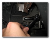
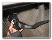
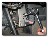
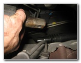
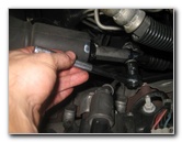
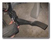
| The first two steps
are to locate the lower end of the intermediate steering shaft in the engine
bay and then locate the upper end in the passenger compartment below the
steering column. If your Tahoe has the power adjustable accelerator pedal, you will need to remove the pedal and the metal mounting bracket in order to pull out the ISS through the firewall. If your SUV or truck does not have an adjustable gas pedal and it looks like you have plenty of room under the dashboard to pull out the ISS, you can skip ahead to further down the page. Loosen the two exposed metal nuts on the metal gas pedal bracket by turning them counterclockwise with the 10mm socket and 1/4" drive ratcheting wrench. There is one nut on the left side of the pedal and the other is at the bottom by the carpet. |
||
 Left Side & Bottom Nut |
 Gas Pedal - 10mm Bolts |
 Top 10mm Bolt |
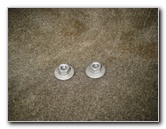
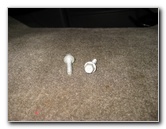
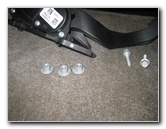
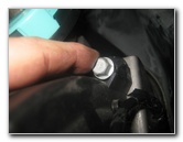
| Set the two nuts
aside in a safe place. There is a third 10mm nut that holds the metal bracket in place. It is hidden behind the gas pedal. So do not attempt to remove the bracket from the firewall. Then remove the two 10mm bolts that hold the black plastic accelerator pedal assembly to the metal bracket by turning them counterclockwise. |
||
 Two 10mm Bolts Removed |
 Pull Off Gas Pedal |
 Electrical Connector |
| Set the two 10mm
bolts aside in a safe place and pull the black plastic gas pedal assembly
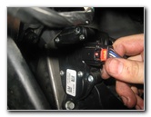
off the metal bracket. Slide out the red locking tab on the electrical connector at the top of the assembly. |
||
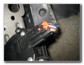 Slide Out Red Lock Tab |
 Disconnect Power Plug |
 3rd Nut Behind Bracket |
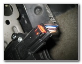
| Once the red lock
tab is out, you can press down on the release tab and pull the power plug
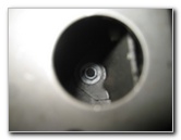
straight out of its socket. Set the accelerator pedal assembly aside in a safe place. Now that the gas pedal is out of the way, you'll be able to see the 3rd 10mm nut through the round hole in the bracket. |
||
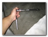 Extension Bar On Wrench |
 Loosen 3rd Bracket Nut |
 3 Nuts & 2 Bolts |
| Attach a 10mm
socket and 6" extension bar to the ratcheting wrench. Loosen the third 10mm nut behind the metal bracket by turning it counterclockwise. |
||
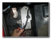
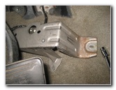 Pull Off Metal Bracket |
 ISS Under Dashboard |
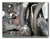
 ISS In Engine Bay |
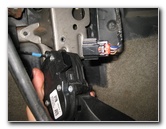
| Gently pull the
metal bracket off the firewall.
Try to avoid stressing or pulling too hard on the wires that will remain attached to the bracket.
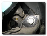
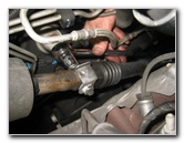
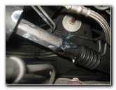
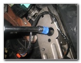
Turning the steering wheel while the ISS is disconnected will cause damage to the SIR coil. The "SIR" or "Steering Wheel Inflatable Restraint" module coil controls the steering wheel air bag. The SIR coil (also known as the "Supplemental Inflatable Restraint" or "clock spring" allows the wires for the steering wheel air bag to turn with the steering shaft. If the wires or the coil are damaged, your air bag light will come on. Check the position of the 15mm bolt and bracket with a welded on nut on the lower part of the intermediate steering shaft in the engine bay. |
||
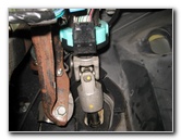
 Turn Wheel Slightly |
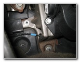
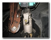
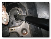
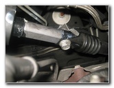
 15mm Bolt Head On Top |
 Loosen Counterclockwise |
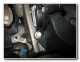
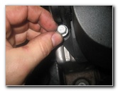
| Turn the steering
wheel slightly to one direction until the top of the 15mm bolt head in the
engine bay is facing up towards the hood. Attach the 6" extension bar to the 15mm socket and 3/8" drive ratcheting wrench. Loosen the 15mm bolt at the lower end of the ISS in the engine bay a few turns in the counterclockwise direction. Do not entirely remove the bolt. Leave the bolt attached to the bracket by at least a few turns. |
||
 Leave Bolt In Place! |
 Interior End of ISS |
 Turn Wheel - 15mm Nut |
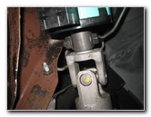
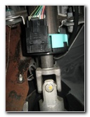
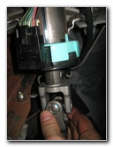
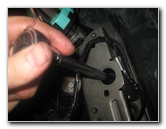
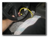
| Move to the
interior of the vehicle and check the position of the 15mm nut and 13mm bolt
head at the top part of the ISS. Slightly turn the steering wheel until the 15mm nut is facing down towards the floor mat. |
||
 Loosen 15mm Nut |
 Secure Steering Wheel |
 15mm Nut & 13mm Bolt |
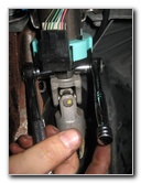
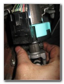
| Loosen the 15mm nut
a few turns in the counterclockwise direction. Do not fully remove the nut. Secure the steering wheel in place with a bungee cord or rope attached to the metal brackets under the driver's seat. GM sells a special tool for securing the steering wheel in place, but it is not necessary. The special tool is the GM Steering Column Anti-Rotation Pin J-42640. It should be OK if the steering wheel moves an inch or two in either direction, but ideally it should not be moved at all. |
||
 Loosen Interior Nut & Bolt |
 Spin Off 15mm Nut |
 Slide Out 13mm Bolt |
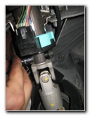
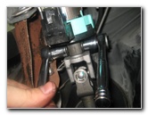
| Double check that
the steering wheel is secure!
Continue loosening the 15mm nut under the dashboard in the counterclockwise direction while holding the 13mm bolt head on the other side in place with a wrench or another socket and ratcheting wrench. Remove the nut and slide the bolt out of the upper part of the ISS. Set the nut and bolt aside in a safe place. |
||
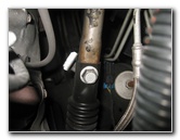
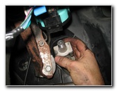
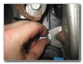
 Loosen Engine Bay 15mm Bolt |
 Spin Out Bolt - Hold Bracket |
 15mm Bolt & Nut Bracket |
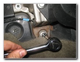
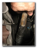
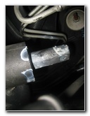
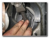
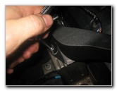
| Then move to the
engine bay and continue loosening the 15mm bolt in the counterclockwise
direction. Hold the metal bracket with the nut welded on to it with your hand while spinning out the 15mm bolt the rest of the way by hand to prevent from having fall down in to the engine bay. Set the bracket and 15mm bolt aside in a safe place. |
||
|
|
||
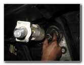
 Separate From Lower Shaft |
 ISS Separated In Engine Bay |
 Interior - Pull Through Firewall |
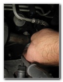
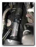
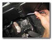
| Carefully pull the
bottom end of the ISS out of the lower steering shaft. Gently allow the lower steering shaft to rest at the bottom of the engine bay. |
||
 Pulling Out From Inside |
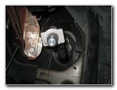
 Hole In Firewall |
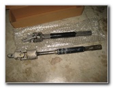 Old Shaft & New Dorman |
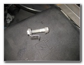
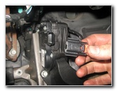
| Move to the inside
of the vehicle and carefully pull the intermediate steering shaft through
the firewall. Don't be alarmed if you notice that the new shaft is shorter than the old one. The new shaft telescopes out to be the same size. |
||
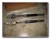 Slide Out - Same Length |
 Insert New Shaft |
 Push Through Firewall |
| Push the lower end of the new Dorman # 425-176 ISS through the hole in the firewall. | ||
 Insert In To Steering Column |
 Insert 13mm Bolt |
 Tighten 15mm Nut Clockwise |
| Insert the top part
of the new ISS in to the steering column. Replace the 13mm bolt and spin on the 15mm nut a few turns in the clockwise direction to hold the upper part of the shaft in place. Continue tightening the nut in the clockwise direction with the 15mm socket and ratcheting wrench to just past hand tight or about 37 ft-lbs of torque. If the bolt head spins as you are tightening the 15mm nut, hold it in place with a 13mm wrench. |
||
 Apply Some Grease |
 Re-Connect Shafts |
 Push From Inside |
| I'd recommend
applying some grease to the bottom end of the new ISS to make it easier to
install it in to the lower steering shaft.
Line up the bottom end of the ISS with the lower steering shaft and push them together. I found it easiest to push the ISS from the inside of the vehicle under the dashboard. |
||
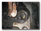
 Bolt Holes Lined Up |
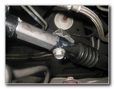 Spin In 15mm Bolt |
 Tighten Clockwise |
| If necessary, use a
screwdriver to force the bolt holes in the ISS and lower steering shaft to
line up together. Re-insert the 15mm bolt and hold the metal bracket in place while you spin it a few turns in the clockwise direction. Continue tightening the bolt in the clockwise direction with the 15mm socket and ratcheting wrench to just past hand tight or about 37 ft-lbs of torque if you have a torque wrench. |
||
 New Shaft Secured |
 Line Up Gas Pedal Bracket |
 Spin On 10mm Nuts |
| Double check that
the fasteners at the top and bottom of the new intermediate steering shaft
are tight before moving on to the next steps. If you removed the adjustable gas pedal assembly and bracket, continue with the following instructions. Line up the metal accelerator pedal mounting bracket and spin on the two 10mm nuts in the clockwise direction by hand. |
||
 Spin On Clockwise |
 Tighten With 10mm Socket |
 Tighten Left Side Nut |
| Tighten the two nuts in the clockwise direction with the 10mm socket and ratcheting wrench to just past hand tight. | ||
 3rd Nut - Attach With Tape |
 Insert In To Hole |
 Tighten Nut Clockwise |
| The easiest way to
replace the 3rd 10mm nut behind the metal bracket is to lightly attach it to
the socket with some tape. I used blue painter's tape but you can use regular Scotch tape, duct tape, masking tape or electrical tape. Insert the extension through the round hole in the bracket and tighten the nut in the clockwise direction until it is snug. Double check that the three nuts holding the accelerator pedal mount in place are secure before moving on to the next steps. |
||
 Line Up Gas Pedal |
 Spin In 10mm Bolts |
 Replace Left Side Bolt |
| Line up the black
plastic adjustable accelerator pedal assembly and push it in to place on the
metal mounting bracket. Spin in the two 10mm bolts in the clockwise direction by hand. |
||
 Tighten Clockwise |
 Tighten Top Bolt |
 Electrical Connector |
| Tighten the two
bolts in the clockwise direction with the 10mm socket and ratcheting wrench
until they are snug. Try to avoid over tightening the two bolts to prevent from cracking the plastic base of the accelerator assembly. |
||
 Push On Plug - Lock Tab |
 Gas Pedal Replaced |
 Remove Bungee Cord |
| Push the electrical
connector straight in to its socket. Slide in the red locking tab to secure the connector in place. Now that the new intermediate steering shaft has been installed, you can remove the bungee cord or rope holding the steering wheel in place. To test the new ISS, take your SUV for a test
drive and enjoy steering with out the annoying "clunk" or "pop" sounds.
Be sure to record the ISS change in your vehicle's service records. For more, check out my other
2000-2006 GM Chevrolet Tahoe DIY Repair & Maintenance Guides. |
||
| If you found this guide to be helpful,
please consider making a small donation by clicking on the PayPal.com
"Donate" button located to the right of this paragraph. Thank you!
(Note: I am not a registered charity. Donations are not tax deductible.) |